|
|
FAQ's
First, don't skip the instructions. There
is a lot of functionality in this little device, so expect to do a
little more than just plug it in. The time spent may just
prevent a crash one day. Have a comment or a question not
answered here, email us. Also
check out VoltMagic
simplified by Ron Lund of HeliProz
South.
 | After
a fresh charge on a battery (LiPo, A123/LiFe, or NiMh/NiCd), the top
green LED is lit. After the first flight it's usually on the
second to last green LED. Is this normal?
Yes, battery voltage drops off quickly at first, then very slowly, until it starts to drop off faster as the end of the
charge approaches. Voltage at the top is a good
indicator that the battery was charged recently.

|
|
How do I decide what
Average Voltage range to
use for my battery?
Tech
Tip: At about 45% capacity, it should typically be on the last green LED
after turning on the radio and stirring the sticks. You could
discharge to this level and set the Averaged Voltage
range so it's on the last green LED.
 Click the chart at left for A123, NiMh, NiCd examples. For best precision, do this
test with a charger that reads out the mAH charged or
discharged:
First, fully charge the battery and then discharge it to about
45% of capacity using the charger. Now discharge the battery further using the servos until the yellow LED stays on. The most repeatable reading is with the servos at idle, but after some load (stirring the sticks). For future reference, take a quick reading with an accurate loaded voltmeter (2 decimal place resolution), then discharge the remaining mAH on the charger and note the mAH reading. If desired, change the AV range of VoltMagic up or down and repeat the test.
Click the chart at left for A123, NiMh, NiCd examples. For best precision, do this
test with a charger that reads out the mAH charged or
discharged:
First, fully charge the battery and then discharge it to about
45% of capacity using the charger. Now discharge the battery further using the servos until the yellow LED stays on. The most repeatable reading is with the servos at idle, but after some load (stirring the sticks). For future reference, take a quick reading with an accurate loaded voltmeter (2 decimal place resolution), then discharge the remaining mAH on the charger and note the mAH reading. If desired, change the AV range of VoltMagic up or down and repeat the test.
|
| I
have the newer version with normal and low range
PLV.
With Normal Range PLV it blinks yellow or red, but on Low Range
it's good. Should I use Low Range PLV, or upgrade the
battery, regulator, or switch harness?
It's up to the pilot. High power servos often make it very hard to keep the peak low voltage out of the yellow or red using Normal Range PLV.
In this case, we generally recommend to configure for Low Range PLV.
(see Table
2 for the trigger points). NOTE:
For Low Range PLV with the 4-cell or regulator ranges, the first
yellow PLV alert is 3.8 volts.
This is the same voltage at which some manufacturers initiate their
battery failsafe IF a time delay period elapses. The voltage will spike below 3.8 momentarily BEFORE it
stays low long enough to initiate the battery
failsafe. Absolute minimum voltage requirements vary, and manufacturer’s ratings may not include this information. Some airborne equipment
may require 3.5 volts (or more), some may tolerate 3.0 volts.
The failure mode from momentary undervoltage also varies
widely. Notable is the reconnect time for some types of receivers
(see 2.4 GHz).
If LED’s 5-8 still blink with Low Range
PLV selected, see Troubleshooting low PLV and the next
FAQ below.
|
| My airplane or heli has PLV
(Peak Low Voltage)
blinking at the red
LED when the battery has plenty of capacity left. It
will even blink the red LED on the ground if I wiggle
the sticks fast. The battery checks fine with my loaded
battery tester (ESV). I've been flying it this way for a while, so it must be OK -- right?
Troubleshooting low PLV -
click here
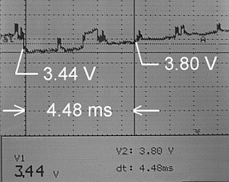
Here's a graph of what can happen to voltage. This example is from a regulator
and
Li battery setup with five digital servos moving
simultaneously on the bench without load. The voltage was 5.2 with
the servos at idle, and the 4000mah Li battery was >7.2V
under a 1 amp load, so it appeared satisfactory -- EXCEPT that
VoltMagic had two blinks on the lowest red LED from simply stirring
the sticks. Obviously, un-regulated battery setups can have
the same issues. This is just an example to illustrate what Voltmagic
detects that common methods don't. At
over 1000 samples per
second, VoltMagic catches the true PLV that slow hobby meters
and data-loggers can't. And, VoltMagic catches these on
the ground during a pre-flight when they are just a couple milliseconds
long. Stirring the sticks at preflight, which quickly reverses
the servo motors, causes maximum current for a very short
time. It's a preview of what will happen in-flight that
only a fast device like VoltMagic can see.
First, double check that VoltMagic is configured for the right
range. The LED pattern for the configured range is
displayed on power up at the end of the LED test. If the range is correct, it's trying to tell you something.
Most airborne equipment will still function down to a bit
under 3.6 volts, but safety margins are like insurance, there
when you need them. Note: Since
5-Cell Ni and 2-cell Li packs
(without a regulator) run at higher voltages, more voltage
drop can be tolerated. However, this could lead to not
detecting problems early enough, so the PLV trigger points are
raised appropriately for these ranges. Current VoltMagic
versions include Normal and Low Range PLV to
further customize the monitor to your setup.
Short explanation for Low PLV:
For the given servo load,
the battery, regulator, switch and/or connecters are not
keeping the voltage above the indicated PLV. Note that
the PLV must actually go lower than the trigger point for the
appropriate LED to blink.
Hint:
If the PLV is still low after configuring VoltMagic for Low Range PLV,
the most common cause is that the battery has too much
internal resistance (high impedance) for the servos.
This is what causes voltage drop from a battery as current
increases. Most
hobby store batteries (even lithium ion for regulators) are
marginal or worse with multiple digital servos.
|
| Why is the PLV (Peak Low
Voltage) scaled differently the the AV (Averaged Voltage)? Why
does a blink on a particular LED not
mean the same voltage as when lit steady?
It could take over 20 LEDs to cover the spread from highest to
lowest voltage in 0.1 volt increments, so blinking is a
space-saver. Also, color is a factor -- 4.7
volts is low (red) for Averaged
Voltage, but it's exceptionally high as PLV goes. So
using blinks for PLV with a different scaling makes a lot of
sense.
You could keep a copy of Table
2 in your field box and hi-lite
the range it's set for. The
color of the blinking LED gives a quick indication of severity
level, so knowing the precise voltage isn't necessary to spot
a problem quickly. |
|
When it's cold, the PLV (peak low voltage) is in the
yellow or red when I "stirred the sticks" on
pre-flight. Indoors it was back to
normal. Are batteries that sensitive to temperature?
Different batteries will handle temperature differently,
but generally batteries are best on a warm day. A good
pre-flight should include rapidly moving the servos and
checking the PLV. |
|
My airplane or heli has PLV (peak low voltage)
blinking at the yellow LED about when I normally
charge the battery. Is this common?
Often that's the case. It depends on the current load of
the servos, discharge curve of the battery, and the associated
voltage drops in the system. |
| Can batteries
wear out and have less voltage with the same maH?
Yes, due to increased internal resistance. VoltMagic typically
shows a lower battery voltage, and/or lower Peak Low
Voltage. It looks like the battery needs charging, even
though it has plenty of maH remaining. Sometimes it happens
gradually over the life of the battery, but not always.
Here's an example: A particular 4-cell
pack was reading much lower on VoltMagic then it had the
previous flying season, but it cycled on the charger within 2%
of rated maH capacity. It measured 255 mOhms using a
1000 Hz impedance test compared with 55 mOhms for a one year
old pack with the same cells. Similarly, using the IR test on a 1010B+
Charger (3.09 firmware) the results were 301 mOhms compared
with 80 mOhms. These tests were at full charge, 20 deg
C (68 F), and include connector and wiring resistance.
|
| Will adding a capacitor
raise the PLV? I've seen this on the internet, it had a
plug like a servo so it plugged into the receiver.
This may help with very short duration transients, especially with a BEC or Regulator. We tested an
ESC with an
internal BEC in a 450 size heli (with 3 Hitec HS65MG on the
swash and a JR 3400g on the tail). There was about 0.2 volt
higher PLV with a 470uf capacitor plugged into the
receiver, but results can vary widely depending on the
particular BEC/Regulator and the servos. Make sure
the voltage rating is higher than the maximum voltage plus a
safety margin of about 2:1 or higher -- The failure mode of a
capacitor could
be a short circuit with near zero volts resulting. We made
ours from an old battery lead and a 16 volt, 470uf radial
capacitor. 470uf is relatively small, the larger the
value the more effective it will be. We've read reports
of 1000uf per digital servo being a good starting point. If you want to try this, make sure the
polarity is correct on the capacitor when you solder the wires
to it. |
Above
is a 5 amp discharge test of a Sanyo 1950FAUP (black) and a
generic 2700 maH battery pack with "A" size cells (red). 5 amps is
an arbitrary choice to illustrate differences in batteries, every
setup will have a different peak current. At higher peak
currents, voltages would be lower then the graph shows (and vice
versa). Even though average current is
usually less, peaks of 5 amps would
cause a voltage drop to the level shown in the graph. (Also
note that a battery has capacitance that tends to dampen
extremely fast voltage fluctuations.) Only the voltage drop of a single R/C
connector on the battery is included on the graph. A
switch or connecter with excessive resistance could make either battery
significantly lower. VoltMagic is looking for these problems when
you stir the sticks on pre-flight, and while you fly. Without
VoltMagic, you could probably fly the "red line" for
quite a while and not even know how little safety margin was
left. The same potential exists for voltage
regulators.
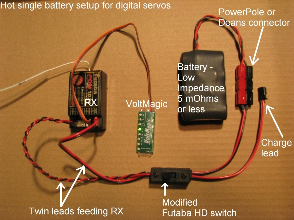
| What about DUAL batteries?
How are they better?
Dual
batteries packs in parallel, each with their own switch
harness, are basically twice as good. The voltage
drop is half of what the same single pack would be, and the
mAH is double. Good choice for larger aircraft.
|
| I've read on the internet to not
use NiMh batteries because they have more voltage drop then
NiCd batteries, is this true?
The battery chemistry, NiMh or NiCd, tell you nothing about
the impedance or the voltage drop under load. Either
type can be made for slow discharge and low amps, or fast discharge and high amps. The latter is what you likely want for digital
servos, the lower the impedance the better they'll maintain
voltage.
When NiMh first came out they were mostly slow discharge, so that's the reputation they
started with, and it still haunts them today. Actually,
some of the lowest
impedance cells are NiMh.
Side note: More mAH doesn't necessarily mean less
voltage drop either. Bottom line, If you measure the
PLV, you don't have to guess about minimum voltage. |
| I'm having trouble getting into configuration mode; what
might be the problem?
The instructions say to continuously toggle the channel
connected to VoltMagic back and forth
quickly during the first 3 seconds after power up until green LED 1 starts blinking
(LED 1 blinks continuously during configuration). Then,
toggle the channel slowly to step through the choices.
"Quickly" and "during the first 3
seconds..." are the key words. You can also plug a
servo in place of VoltMagic, then verify it moves with the
correct switch or control.
Also note that the ATV/End Points for the channel connected to
VoltMagic have to be 85% (or more) to enter
configuration. Check transmitter programming for any
mixes or settings that might affect the channel. |
| With Lithium
(LiPo) batteries and a
voltage regulator, where should VoltMagic be connected?
While VoltMagic can monitor the two cell Li battery itself
(good for testing if the battery voltage is sagging too much
under load), the best place is connected to the receiver so it
can monitor the output of
the voltage regulator and check for glitches or failsafes.
If the Li battery dips too low at the input
of the regulator, it will show up as low voltage at the
output. Regulators require the input voltage to be higher,
often at least 1 volt greater than the output. Of course, the ideal setup is with servos that
handle the voltage without a regulator.
If you want to monitor a Li battery powering a regulator, the
balance tap may be convenient for connection. A micro
receiver switch can be adapted, one side to the balance tap
and the other connected to VoltMagic. |
| I'm testing the glitch detection by turning the
transmitter off, or by turning on another transmitter on the
same frequency. It doesn't seem to work unless I leave
the transmitter and receiver on for a minute before testing,
why?
VoltMagic checks for the existence of servo pulses after one
minute of operation. If pulses exist, glitch (or
failsafe) detection is enabled at that time. The one
minute delay allows time for turning on the transmitter, noise
from a glow plug connector, etc.
Note that with 2.4 GHz and PCM radios, a glitch (i.e.
missing or abnormal signal pulse) is from a receiver failure
(possibly a reboot). It's not related to the transmitter
and can't be tested by turning the transmitter off. |
| I'd like to use VoltMagic's Failsafe
Detection, but
I'm having trouble setting up the failsafe (for the channel
connected to VoltMagic) on my transmitter.
Every transmitter has a slightly different procedure for
setting a failsafe. If you haven't already, read the
section in your transmitter's manual regarding failsafe
setting. There are usually two types of failsafes that
you can select for each channel: "hold last
position" and "preset position." The
"preset position" is what you want for VoltMagic and
your throttle (idle). All the radios we have seen
require that you use a switch, dial, or joystick to set the
particular channel(s) to a desired position, then press
something to memorize that position as the failsafe.
Most radios set one channel at a time, but some set all the
channels at once. The term "position" is used
because typically we're talking about a servo, but in the case
of VoltMagic it's just a signal. The
"position" that VoltMagic will count as a failsafe
is full maximum (not 100% but the max endpoint or ATV
for the radio) in either direction. If the channel
uses a two position switch, either position will work.
If the channel uses a dial, full clockwise or anti-clockwise
will work. Double
check that you don't accidentally have a Pmix or other
function acting on the channel. After the failsafe
position is set to this maximum value, the end point or ATV
must be reduced (to 85%) so the switch or dial doesn't put the
signal going to VoltMagic in the failsafe zone and create a
false alarm. There is no point in repeating the
VoltMagic Installation Instructions here, so read the
section on Glitch or PCM Failsafe Detection
and then follow the steps.
Notes for Futaba 9C radios (typical
of many radios).
Check that the THR>NEEDL mixing and GOVERNOR function are
either inhibited, or not using the channel VoltMagic is
connected to (pages 58 & 97 of the manual). There is
also some important info on page 39 about functions that can
take over a channel. On page 43 is the Failsafe setting
procedure. Note that you have to select the channel on the
screen (each channel is set separately) AND you have to hold
down the "wheel" for greater then 1 second
to confirm. The transmitter sends the failsafe settings
at 2 minute intervals, so wait 2 minutes before turning the TX
off for a test.
Notes for Futaba 9Z radios
Channel 9 doesn't have a failsafe position, use channel 7 or 8
and use 9 for something that doesn't need a failsafe (e.g.
governor on/off). Failsafe positions for the 9Z are
set individually for each channel (hold last position is also
an option for each channel). For the VoltMagic channel, set the AFR
(Adjustable Function Rate) to 100% in both directions for all
flight conditions. Set the ATV for the
VoltMagic channel to 140% on both sides, then set the
failsafe, which should read plus or minus 100% on the F/S
screen (the ATV and failsafe are scaled differently).
The switch (or control) for VoltMagic must not be in a
mid position when setting the failsafe. After setting
the failsafe, set the ATV to 85% on both sides for all
flight conditions. LIM mode for ATV is preferred
because AFR or PMX will not drive the signal into the failsafe
zone (useful if the channel is shared with something that
doesn't mind the VoltMagic failsafe position).
Notes for JR 10X radios
Failsafe is code 77. The options are different depending
on whether ZPCM or SPCM is selected (hold last position is an
option for each channel with SPCM). Channels 9 and 10 do
not have a failsafe position, use channel 7 or 8 and use 9 and
10 for something that doesn't need a failsafe (e.g. governor
on/off). Since failsafe positions for the 10X are all
set at the same time, ensure the throttle is set to idle and
the other controls are where you want them. Set the ATV
for the VoltMagic channel to 150% on both sides, then set the
failsafe. The switch (or control) for VoltMagic must not
be in a mid position when setting the failsafe.
After setting the failsafe, set the ATV to 85% on both sides.
Notes for JR, Spektrum, and Futaba 2.4 GHz systems
The higher end models (e.g. Futaba 8+ and the
JR 12+ channel 2.4 GHz receivers) have Failsafe Positions for
all channels, so counting failsafes is possible with
VoltMagic. Just follow the instructions in the applicable
radio manual and the VoltMagic configuration guide. Note
that counting Failsafes is optional, see below.
For radio systems that can't set failsafe positions for
channels other then throttle, leave VoltMagic set for
"Glitch" mode. VoltMagic will still count abnormal or missing pulses which should NEVER happen with a any 2.4 or PCM
system that is operating correctly. If this happens the RX may be faulty,
or perhaps it rebooted.
Spektrum AR7100R receiver
with built-in RevLimit governor: Don't plug VoltMagic
into the spare throttle channel if the built-in RevLimit is
used, otherwise glitches will be counted (LED 1 blinking)
during RevLimit operation. Spektrum may change firmware,
and there is no harm in trying this. |
| My transmitter doesn't have ATV (end point) adjustment
OR failsafe setting for channel X. Can I use FAILSAFE
detection on channel X? (Often channel 9 or higher).
The short answer is no. Some receivers like the R149DP
have channel 9
combined with the battery input (marked 9/B). You can
plug the battery into the connecter marked DSC to free up the
channel 9 slot. If 7 and 8 are currently in use, move
one of them to 9 to free it up for VoltMagic. (The DSC
slot can also be used with a dual battery setup.) |
| Is stirring
the sticks and checking the PLV with VoltMagic on
pre-flight really worth doing? Aren't the voltage dips
going to be much lower under load while flying?
Quick reversal of a servo's direction causes current spikes
that approximate actual flying. If your battery is getting
low and the PLV is blinking after a flight, try this: Stir
the sticks and compare
the PLV (Peak Low Voltage) to what you had while flying. If
your not an super aggressive pilot, the PLV on the ground may actually be lower! The duration of the dips is longer
under load, but the voltage at the bottom of the dip is
usually close to the same.
NOTE: Common hobby data-loggers,
watt-meters, and multi-meters are usually too slow, and don't
indicate the true minimum voltage (PLV). A
scope will give
comparable results to VoltMagic, but the price tag is pretty
high, there's no glitch or failsafe counting, and the flying
weight is tremendous. 
|
| Where is a good place to mount VoltMagic on a heli without
a clear window in the canopy?
Here's a picture of a MinAir Fury with VoltMagic double-stick
tape mounted to the left engine mount.
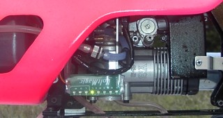
Avoid servo extensions and keep the wires away from the fan
area. If you mount it upside down, it's easier to read
while hovering inverted.  |
| What are some ideas to reduce or eliminate glitches?
Glitches can be caused by the transmitter, receiver, external
interference, or interference caused by the aircraft.
Always check the radio equipment on the ground for proper
range, then use VoltMagic to detect glitches while moving the
transmitter antenna, etc. Route the receiver antenna
away from the aircraft as much as possible and avoid things
that would shield it or introduce noise. Interference
from the model itself is typically from loose
parts rubbing and/or static discharge. |
| Does VoltMagic eliminate using a loaded volt meter?
*
No, and a loaded volt meter is not a substitute for VoltMagic.
The adjustable battery voltage algorithm in VoltMagic is an
excellent indicator, but two types
of testing give the best reliability. The peak low
voltage and glitch counting with VoltMagic are beyond
the scope of a loaded meter; but just as important.
* To accurately use a known load and voltmeter to
estimate battery capacity remaining, the voltage discharge
curve of the battery must be taken into account. Rules
of thumb are often inaccurate and obsolete. |
| Should I try and seal up the
ends on VoltMagic to keep exhaust and oil
out?
No, all that will happen is that you will keep whatever gets
in from draining out. Generally this is just a cosmetic
issue, VoltMagic works fine even immersed in fuel or
oil. Of course, it's best to keep it away from engine exhaust. |
| Do any servo manufacturer's recommend
installing a monitor when using digital servos? Why do
digital servos draw more current?
Yes, Futaba has recommended installing a monitor. See this paper about digital
servos, it's near the bottom. |
|
|


)
)
)